Table of Contents
Ai Example
Visualiser: Moving RGB Matrix
Using Ai to visualise an Artnet-controlled 3D moving matrix, this time with RGB control.
| by: | Sebastian Beutel, July 2015 |
|---|---|
| published: | http://www.avolites.de/support-downloads/ai-projekte |
| tested in version: | made in version 8.0.2, now tested again in 10.2 |
| download: | all_lines.scb patch file (41 MB) |
Hint: click the images to show them larger.
This project is based on a similar idea like Visualiser: Moving Matrix. However, this time each object is individually RGB-controlled, and a separate window for the RGB mapping is rendered as well.
It is recommendable to read and understand the other project, before delving into the RGB thing.
Background
Again we had a moving object to visualise: a matrix comprising of spheres, hung from artnet-controlled winches. This is similar to Visualiser: Moving Matrix. However, this time an enhanced product was used where each sphere could be RGB-controlled by Artnet. And when implementing this into the visualisation project in Ai it was decided to also output a flat colour window, to cross-check the programming.
Again, the solution comprises of a multilayer patch, and it made much sense to define the parameters
- per whole matrix (and for the control window)
- per line (row)
- per individual object
It were 20 lines (rows), each comprising of 16 spheres (which again were modeled as cubes for sake of vertices/performance). And the control window was decided to be 400×320 px so that each sphere/cube was represented by a square of 20×20 px.
Used Modules and Patches
The Patch
As like as in the other example this is something for nesting multiple layers of patching - the core is a 3D Morph Model module, here with coloured texture - and multiple modules are then assembled as groups, some groups make for a line and all the lines create the complete object. This way it's rather easy to only expose the parameters which are really needed to the next level.
Unfolding the Patch
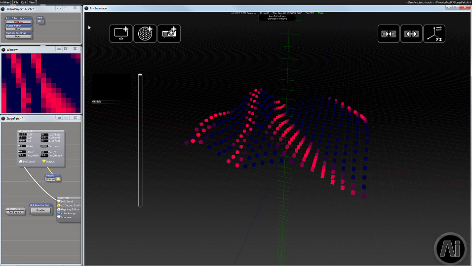
In order to analyze this project load the patch all_lines.scb (see downloads above) into the stage patch, hook the white DMX Sender input into the white DMX Sender output on the main Patch IO, and insert a Window, patch it to the yellow Output port and open it:

The main patch all_lines.scb offers a couple of parameters to be directly set on its surface:
X_0,Y_0andZ_0define the overall position of the object in 3D spaceX_OffsetandZ_Offsetset the spacing between rows and columns of the matrixY_Travelsets the max. height travel, i.e. how high the spheres travel between DMX=0% and DMX=100% on the height channelScalesets the relative size of the spheres/cubesTextureis the number of tiles to be rendered in the control windowTex_XandTex_Ydefine the top-left starting point of the texture in the control windowTex_WidthandTex_Heightdefine how large the blocks to be rendered per cube are in the window
Now, let's open all the layers, and find out how this works from the bottom to the top:
- double-click on
all_lines.scbto open it - this contains 20 subpatches
1_line.scb- double-click on one of them - each line consists of 16 subpatches
1_cube.scb- double-click one - this opens the patch per individual cube - the core of the project (we don't explain the patch
Sample Texture Region Simple.scbhere as this is a factory patch, and is explained separately.
1_cube - the inner core

Each cube of the final assembly is created in such a patch:
- the 3D Morph Model is used to load a suitable model - the easiest variant is the default_cube.3ds (click on
Loadand load the file from /Distrib/Models/Default Models) - values for
X Position,Y PositionandZ Positionare calculated on the layers above, hence the ports are directly wired into the Patch IO module X Scale,Y ScaleandZ Scaleare all wired into oneScaleport on the Patch IO as they all get the same value
The other modules are used to create the colour from the RGB values, to apply it to the model, and to create a chunk of the final control window
- Vector Join takes the
Red,GreenandBluevalues from the Patch IO, as well as anAlphavalue which is set as Constant, and joins them into one vector - this vector is sent as
Colorvalue to the Rectangle. This directly creates a coloured rectangle video - however, in order for the cube to appear coloured we need a texture, not a GL render. Hence, the Render To Texture is used. It needs a
Size Inputwhich is a vector, which we create from theTexSizeport of the Patch IO with another Vector Join module. The resulting texture is fed into theTextureport of the 3D Morph Model, and into the Sample Texture Region'sTexture Inport - finally, Sample Texture Region Simple creates a tile of our final control window, with the rendered colour. The required parameters
X Out,Y Out,Out WidthandOut Heightagain come from the Patch IO, and the resulting GL render is sent asOutputto the Patch IO which has the side effect of a closed Render Path to make all other modules behave correctly.
1_line - assembling 16 cubes
Going up one level from the single cubes we get to the line patch - this holds 16 cubes as described above, feeding them their parameters:


The patch 1_line forwards global data from the all_lines patch (top) to the individual cubes (below), and does the Artnet magic. In this case, the assume DMX layout per line/controller is this (derived from an original product):
| channel | description |
|---|---|
| 1 | winch #1 (height) |
| 2 | winch #2 (height) |
| 3 | winch #3 (height) |
| … | winches #4 … #20 (height) |
| 21 | red #1 |
| 22 | green #1 |
| 23 | blue #1 |
| 24 | red #2 |
| 25 | green #2 |
| 26 | blue #2 |
| 27 | red #3 |
| … | colours next pixels |
| 78 | red #20 |
| 79 | green #20 |
| 80 | blue #20 |
(this was originally created with 20 cubes per line which was later reduced to 16).
The input data per cube is produced like this:
X Position Inputis the same value for all cubes per line and comes from Patch IO'sX_0portY Position Inputis calculated from the base height (Y_0), plusY_Travel* the Artnet height channels valueZ Position Inputbegins with Patch IO'sZ_0and is incremented by theZ_Offsetper cubeScale Inputis again the same value for all cubes and stems from theScaleportRed,GreenandBluecome directly from the respective Artnet channelsTexSizestarts with theTexSizevalue and decrements per cube objectX Out,Out WidthandOut Heightare again global values, patched from Patch IO's ports to all cubesY Outis the vertical position of this tile in the control window. It starts atY Outand is incremented byOut Heightper cube- all the
Outputs are successively merged together with the Render Merge modules, and the result returned to Patch IO - the
DMX Sendis patched to all ArtNet Input Large modules - their
Universeport is patched into the Patch IO to allow for easier re-adressing on the higher level
all lines - combining 20 lines to a matrix
The main patch all lines.scb holds all 20 lines of cubes, and feeds them their data.


The Patch IO of this module holds only two ports - for data which needs to be patched through to the main stage patch: DMX Send for the overall ArtNet input which is sent to all lines, and Output which brings the combined control window to the top (and closes the render path). All other parameters which are seen in the top window are created here as constants (top-left), and right-clicking plus Add to Parent Panel brings the text inputs at the very top of the project:
x_0sets the left-right start position, hence the first line gets this asX_0, and all subsequent lines are incremented byx_Off.y_0is the top-down default value which is equal for all lines, and patched to all theirY_0inputs, as isy_Travelwhich sets the maximum travel for DMX=100% on the winch channelz_0(back-front start position),z_OffandScaleare also sent to all linesTexSizestarts with the globally-set value and is decremented by 20 per lineX_Outis the horizontal location in the control window - starts at the globally set value and is incremented by the globalOut_Widthwhich is also forwarded to each lineY_OutandOut_Widthare both distributed to all lines- each line has a designated constant input, to set its universe
- finally,Render Merge modules again merge all lines' outputs together, to allow for the finally completed control window output.
Application
In order to make use of this project import and patch as suggested in Unfolding the Patch (connect DMX Sender and Output, and open a window). You may adjust the values, and add or delete some elements/subpatches to bring it in line with the project at your hands.